


Designing, building and programming the observatory model was an ambitious project that took nearly four months to complete. All of the component parts of the model were designed using AutoDesk’s “TinkerCad” program and subsequently printed out with a 3D printer.
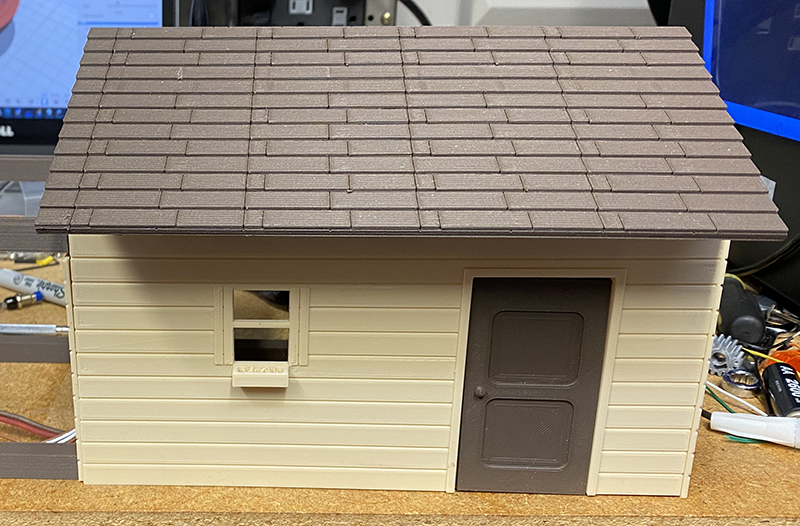
The roof, doors and floor were printed using a special material that contains sintered wood along with plastic to give the parts the look and feel of real wood.
One of the more difficult aspects of designing the model was trying to get all of
the parts to a common scale. This turned out to be a bit more difficult than I had
thought it would be due to having to make room for servos and other components that
are only available in certain sizes. For the telescope drive, I used the smallest
servos that I could find which are GH-
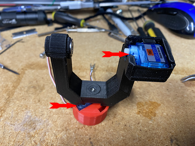
The servo that moves the altitude axis of the model directly drives the scope model via a special mounting plate.
To accommodate the wiring, the right fork arm was designed as a hollow object. In the left arm of the fork, a ball bearing set supports the opposite side of the scope via another mounting plate.
In the base of the mount the azimuth servo directly rotates the fork mount. The mounting base has a slot designed in it to accommodate the wiring for the servos.
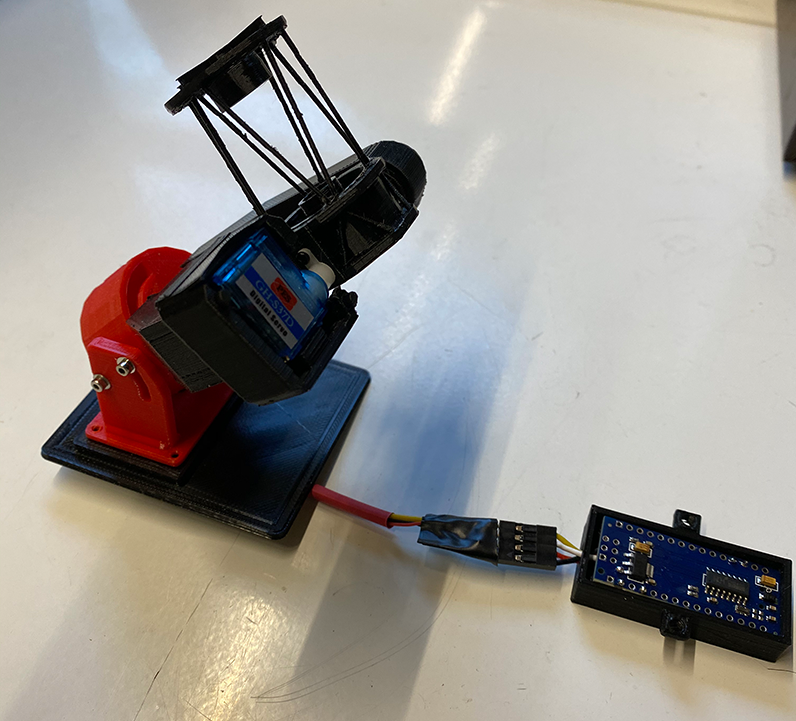
The telescope model itself is loosely based on a carbon truss type scope. Shown above are the scope, the mount, the mounting plate and the microcontroller for the telescope mount. The motion of the scope is controlled by the Arduino Nano microcontroller which is mounted underneath the floor of the observatory model.

The Arduino Nano was programmed to accept and issue motion commands based on the
de-
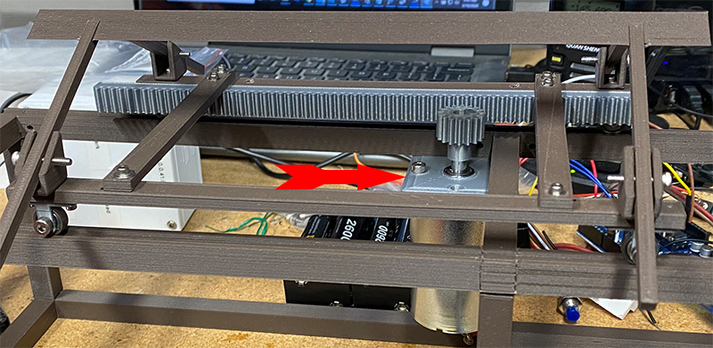
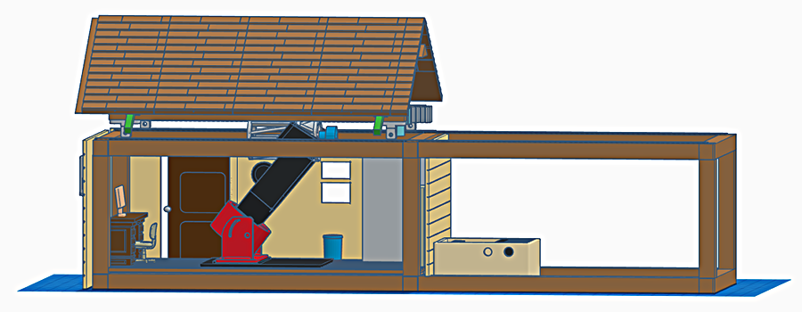
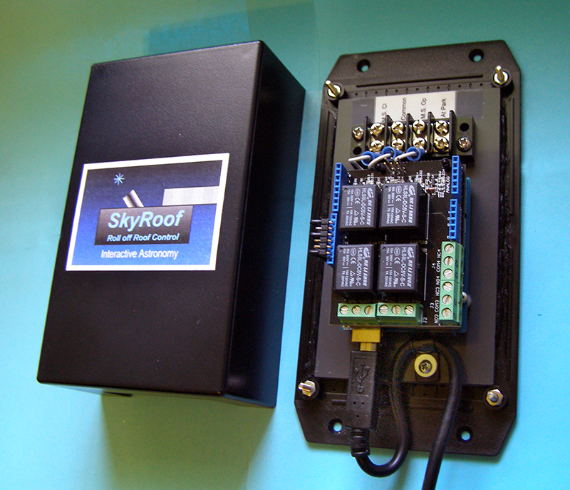
The roof mechanism is driven by a 100 RPM DC motor which drives a rack and pinion
attached to the sliding roof. The roof motor is driven by a motor controller driver
which is controlled by another Arduino micro-
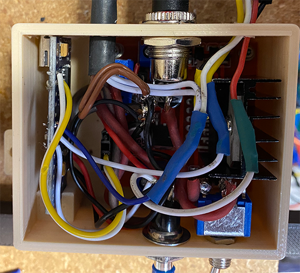
In hindsight, I should have built a slightly larger enclosure to house the driver and Arduino controller. Assembling and soldering the connections was like building a ship in a bottle. On the front side of the enclosure (bottom of photo) is a main power switch along with a push button switch to operate the roof motor manually.
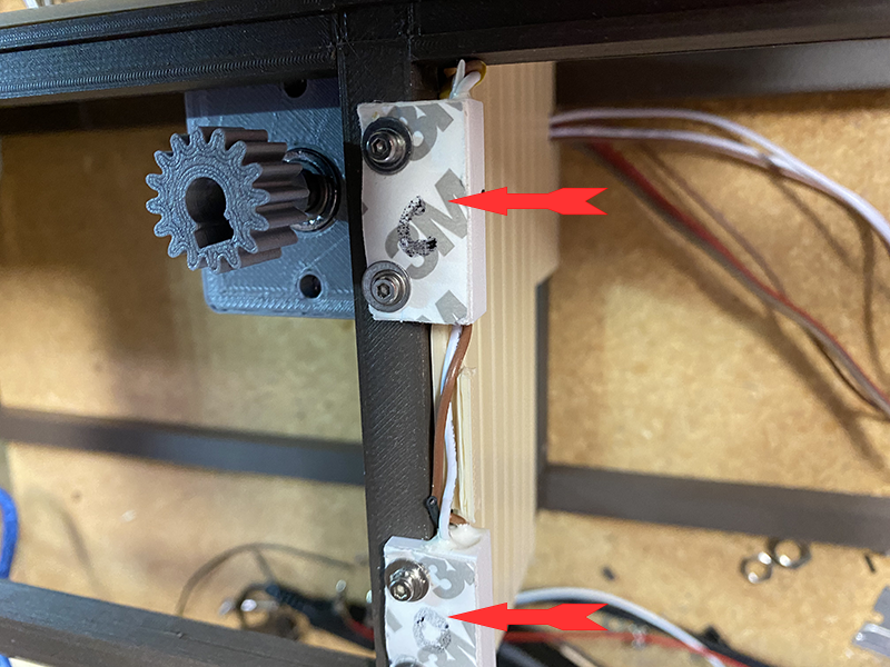
A pair of magnetic sensors are mounted on the roof support structure and a pair of magnets are mounted on the moving roof. When one of the magnets approaches the magnetic sensor, the sensor signals the roof controller to cease moving the roof. This system limits the motion of the roof to prevent it from moving too far in either direction.
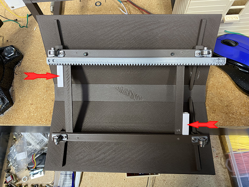
This is the underside of the rolling roof structure. The moving magnets are denoted by the arrows. Also shown are the roof rollers (which are actually very small ball bearing sets) and the gear rack that the motor drives. The roof rollers ride in slots on the top surface of the frame structure.
Wes Jones | 01/12/21
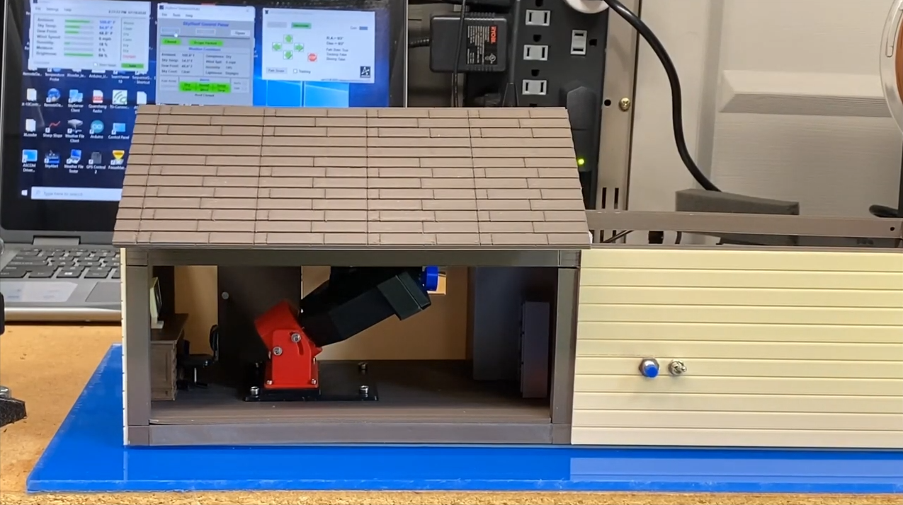
The system is controlled by an off the shelf SkyRoof controller which sends the signals to open and close the roof and to park the scope when necessary.
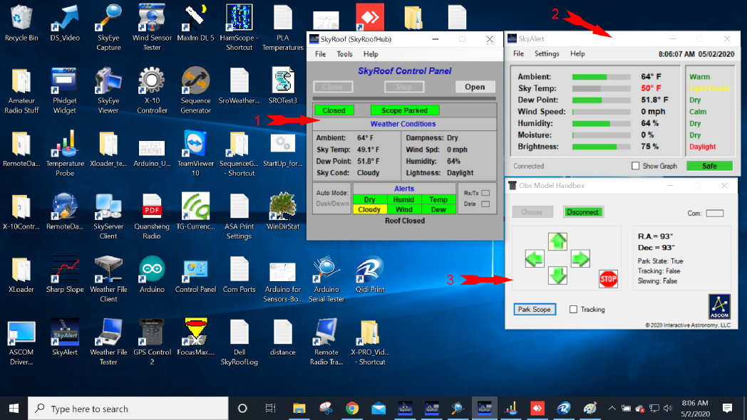
The screen shot above depicts the various software programs being used.
(1) SkyRoof Control Panel-
(2) If the SkyAlert system detects poor weather or other adverse conditions, the SkyRoof program will park the scope (if necessary) and close the roof.
The Obs Model Handbox (3) is an ASCOM compliant custom program that controls the scope movement. It can also park the scope and turn the scope tracking on or off.
Although the schematic wiring diagram may appear complex, the interconnecting wiring between the modules (separated by red dashed lines) is actually fairly simple and uses a minimum amount of wiring.