
I’ve always been fascinated with rotary engines. I purchased my first rotary powered
car in the mid 1970’s which was a Mazda Rx-
Mazda continued production of the rotary engine all the way up until 2012 when the
last Rx-
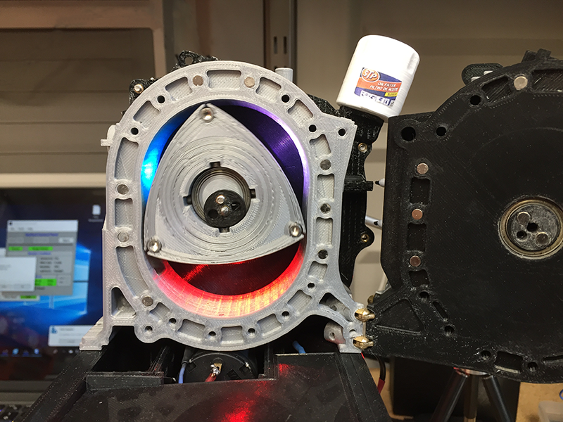
This is the second engine model I’ve made with my 3D printer. Although the rotary engine consists of far fewer parts than the piston engine, this model was much more complex to assemble due to the addition of animated LED’s that change colors according to the combustion cycle while the engine is rotating and the addition of an engine stand.
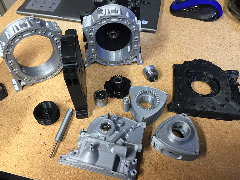
A rotary engine has far fewer parts than a typical piston engine. In fact, there
are basically only three moving parts in a two-
Because of the lower part count and smaller parts, this engine did not require as much printing time (or material) as the Toyota engine model did. Despite this, it still took a lot of time to build the engine because of the addition of electronic components needed to create the combustion animation effect.
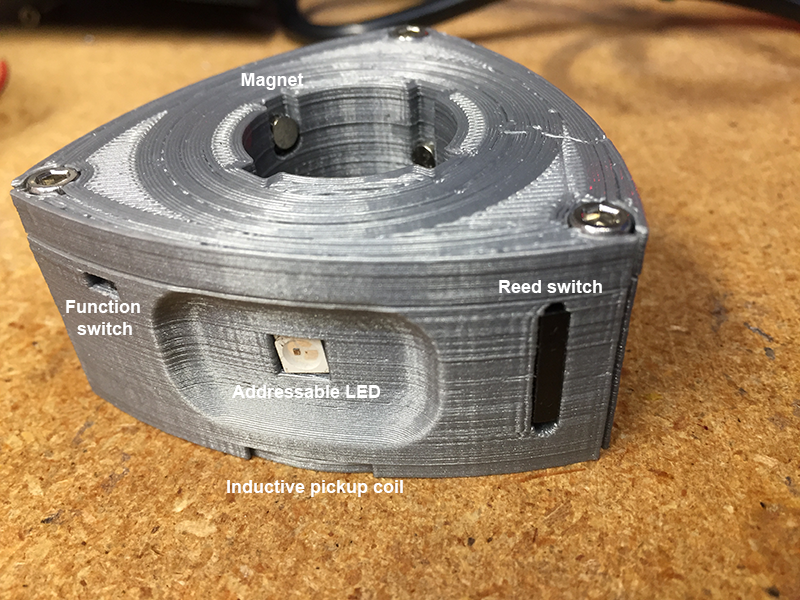
The rear (or #2) rotor of the engine is the rotor that displays the animation effect. Each face of the rotor has an addressable three color LED installed facing the outside of the rotor as shown above. The LED’s are controlled by a microcontroller and circuitry inside of the hollow rotor. A magnetic reed switch on one face of the rotor sends a signal to the microcontroller to trigger the LED color change at the appropriate time. Each time the reed switch passes by a stationary magnet mounted in the side housing, the signal is triggered.
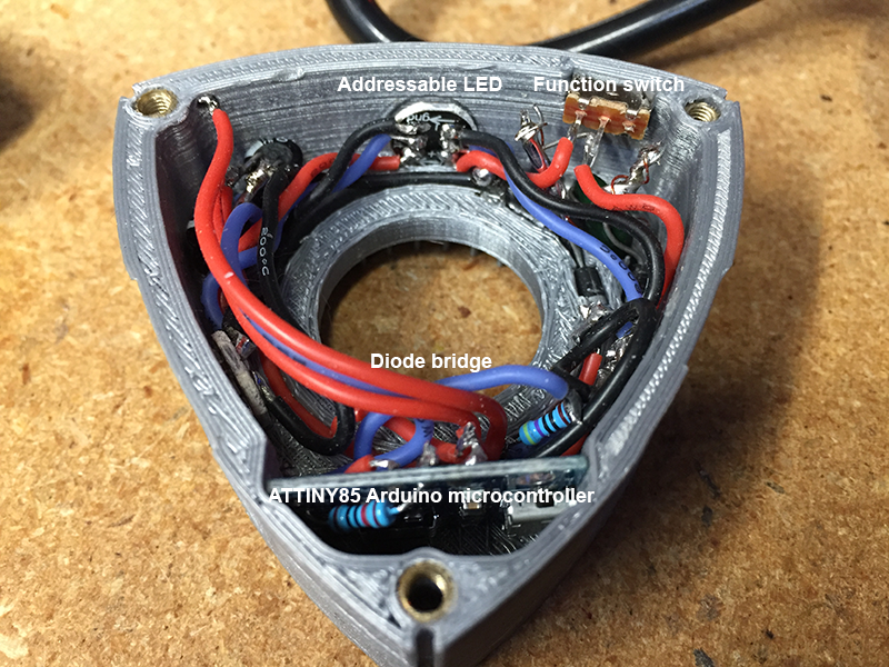
The circuitry inside of the rotor consists of a very small microcontroller, a sliding function switch and a rectifying diode bridge with filtering capacitors. An inductive pickup coil (not shown in photo) resides in the bottom of the rotor. (More on that later).
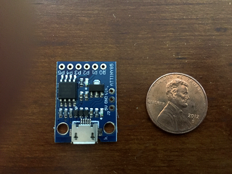
This is the microcontroller that controls the addressable LED’s. Though quite small it has way more than enough processing power to do the job.
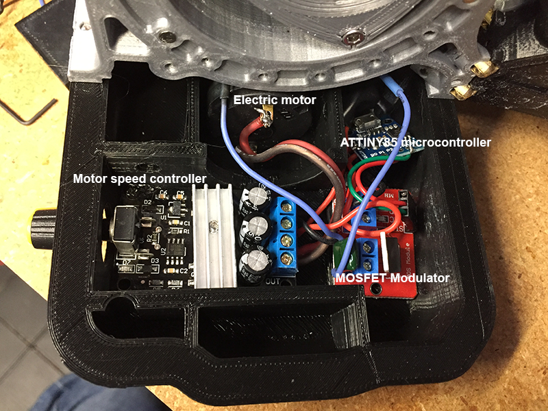
The oil pan houses more electronics. A power jack on the side of the oil pan feeds 12 volts into the circuitry. A PWM speed controller is used to adjust the speed of the electric motor that spins the model. Another ATTINY85 microcontroller sends pulses to a MOSFET modulator which in turn sends voltage pulses to a “transmit” coil mounted at the back of the rear housing. The voltage pulses are picked up by the “pickup” coil mounted in the rear rotor. This creates a transformer of sorts which provides power to the circuitry in the spinning rear rotor wirelessly. This is similar to the method some of the newer smart phones use to charge the battery wirelessly.
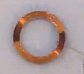
Both the transmit coil and the pickup coil are similar, consisting of about 100 turns of copper magnet wire. Winding the coils was a bit tedious but not difficult.
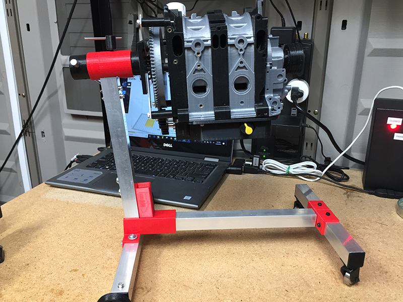
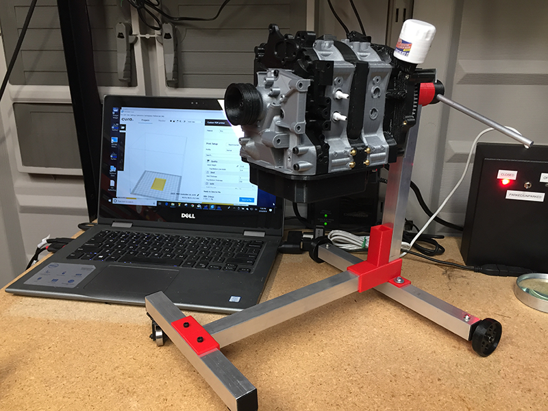
Plans included a design for an engine stand which can be adjusted to accommodate any of the designer’s models.
The engine stand is constructed from 3/4” aluminum stock for the “legs” and upright. All of the brackets are 3D printed with 100% infill for added strength. The rear wheels are printed plastic while the front casters are ball bearing sets.
The model is complete and ready to run...
Click here to see a video of the rotary engine model in action.